Landman Robotics
Landman Robotics is in the business of developing robotics, sensors and other innovative technologies. We take a long term view in all our decisions. We believe that it takes innovative solutions to solve real-world problems. This yields disruptive products with demand. We have identified robotics as a vehicle to part-take in the fourth industrial revolution. We are technically orientated; few excel in this field; this we use it to our advantage.
We are similar
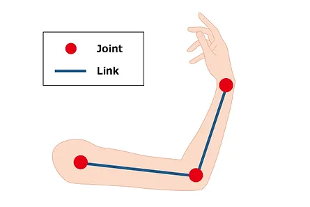
Humans are not that dissimilar from Robots in that they share the same underlying structure of links and joints as shown in the figure. In our limbs parts such as the elbow and knee allow limbs to move freely in similar ways as in robots. In our bodies skeletal muscles are anchored by tendons to bone and are used to effect skeletal movement by the contraction of muscle. In robotic arms links and joints are set in motion by actuators driven by motors.
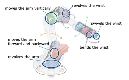
Robots move as we do
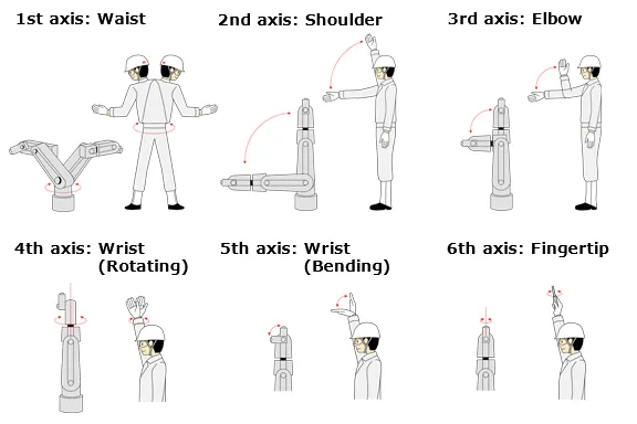
to compare a robotic arm with the human arm in order to understand the basic mechanical movement of a robotic arm. A serial linked robotic arm is typically composed out of 6 joints connected with 6 axes and moves in comparatively similar ways as our own arms do as illustrated in image.
Categories
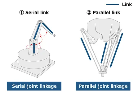
Robotic arms are roughly categorized into two types according to how their links are arranged namely Serial link and Parallel link as shown in the figure. The human arm is categorized as a serial link since its joints - the shoulder, arm and wrist - are aligned in series.
Different Parts
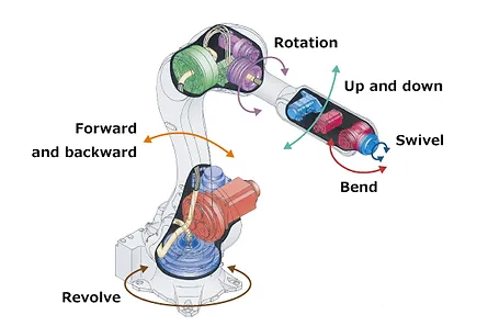
A robotic arm is made up of many different parts as illustrated in the figure. Among those parts are five particularly important ones namely: motor, reduction gearing, transmission, end effector and encoder. Let’s discuss these in more details.
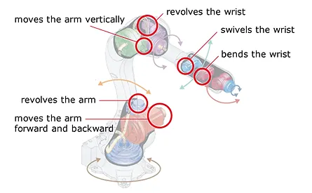
Motor
The motor is the component that allows a robot arm to move up, down and rotate. DC motors are typically employed in robotics due to their compact size in comparison to their power to weight output. Located in close proximity to the joints DC motors along with reduction gearing is responsible for rotating and moving links. The points marked by red circles in the figure.
Gearing
In most Robotic applications speed from the DC motor is reduced with reduction gearing in order to produce more torque. The output shaft of the gearbox rotates at a much lower rate than the input shaft, but with increased torque. Robotic locomotion is typically created with a DC motor attached to reduction geared systems such as sun-and-planetary or strain wave gearing.
Transmission
As stated earlier, motors are typically placed near joints, but in some instances they may be placed far away. In these instances transmission systems such as belts, pulleys and gears are employed in order to transfer mechanical energy. For instance, it is not unusual for the wrist manipulating motor to be located on the elbow joint of the robotic arm and connected to the wrist component via a pulley system as can be seen in the YouTube Video
End effector
Humans can perform various tasks using tools. Similar to humans, swapping the device attached to the robots wrist make a robot highly versatile and able to take on a variety of tasks. This device is called an “end effector”, and there is a vast array of them ready for use. Typical end effectors include suckers for lifting, claws for manipulating, tools for welding and painting etc as illustrated in the YouTube video.
Encoder
A typical robotic arm is fitted with six rotational joints allowing rotation around six separate axes. Angular position sensors known as “rotary encoders” are located at each of the rotational joints and measure the angular position of each joint in real-time.
This information is used by the motion control system to direct six separate control loops in such a way as to steer the system towards a required position. To do this the motion control system receives a “reference input” comprising a specific set of orientation and position data describing the required tool tip position and orientation.
The motion control system then manipulates the robotic arm around each axis, continually considering each axis position as measured by the encoders until the required tool tip position and orientation is reached.
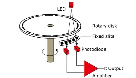
To explain the principle of an encoder consider the workings of a basic optical encoder as depicted. Typical optical encoders have a disk attached to the rotating shaft of the motor.
The disk has slits at regular intervals to block light or let it pass. On one side of the disk we find light-emitting-diodes and the other light receiving photodiodes. When the motor rotates, light either passes through the slits or is blocked. This light (or the absence thereof) is picked up by the light receiving photodiode producing an analogue or digital signal used to determine angular position and rotational speed.